Terrific Audio Driver
Over the past year I built my own homebrew audio driver for the Super Nintendo - The Terrific Audio Driver.1
The initial goals for the audio driver were:
- Keep it simple. Get it working quickly, try not to spend too much time on it.
- No virtual channels. 6 channels are dedicated to music, 2 samples are dedicated to sound effects.
- A bytecode based sound effect and music format.
- No sample swapping.
- The pitches are calculated by the compiler, not the SPC700 code.
- Lots of sequenced sound effects, with the ability to play custom ADSR envelopes in sound effects.
- MML music.
- A custom loader to speed up data loading.
Four months into the project I added sound effects to my Unnamed SNES Game. At the 7th month mark I had a MML compiler written in python and the driver was at a state where I could add music to my game. Sometime during all this I made the decision to rewrite the compiler in rust - partially as an excuse to learn rust but mostly to create a nice GUI where other people could create music and sound effects with my audio driver.
It's been nearly a year and the audio driver is in a good state, there's a nice GUI for editing and previewing both music and sound effects. It does everything I want and more.
The latest release of the Terrific Audio Driver can be found on GitHub.
Samples compiler
Firstly, before I started any spc700 coding, I needed audio samples. BRR seamed like an easy format to make an encoder for and it worked like a charm. My encoder is a simple one, it tries all possible shift and filter values and selects the best one using mean squared error.
Instruments
After creating the wav2brr encoder I experimented with spc700 coding using wiz and got it to output
some test tones. Next, I had to figure out the formulas for calculating the PITCH register values
for various musical notes.
note_frequency = pow(2, (semitones_above_c0 - 57) / 12)) * 440;
pitch = note_frequency / sample_frequency;
pitch_register = int(pitch * 0x1000);
Early on I decided that the compiler will be responsible for calculating the PITCH register values.
I did not want to code this formula in spc700 assembly, nor did I believe I could write a fast
partially-calculated variant without sacrificing speed or accuracy.
The pitches stored a fixed-size split word table.2 Each instrument has a
pitchOffset value, which is added to the noteId (number of semitones above c0) to form the
pitch-table index. This addition is expected to overflow and wrap-around, allowing me to map
instruments to pitch-table indexes and skip multiple octaves with a single 8-bit value.
The pitch table generator is able to merge different instrument frequencies that use the same tuning. For example, the instruments with frequencies 1000 Hz, 500 Hz and 250 Hz will be merged together to reduce the overall size of the pitch-table.
Interestingly, the pitch-table (including the input parameters) is probably the only thing in the audio driver that is unchanged from its original design.

The DSP limits the maximum octave a sample can be played at. Instrument samples tuned to B +21
cents can be increased by maximum of 2 octaves (+1 octave for almost all other tunings).
Additionally, samples played at an excessively high PITCH can have aliasing effects, while samples
played at an excessively low PITCH can loose detail and precision.
The terrific audio driver allows the user to select the octave range of an instrument, based on personal taste. As an advantage this will also decrease the amount of limited pitch-table space used by the instruments.
Dupe block hack
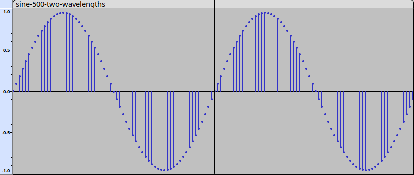
About 8 weeks into the project, I was wondering why my sine wave sample did not sound right. The other test samples (square, sawtooth, triangle) sounded fine. What's happening that causes the sine wave to sound wrong? I looked at the waveform and saw this:

These jagged lines are caused by BRR filter 0 (no-filter). Since the other BRR filters use the previously decoded samples to aid in waveform generation, the first block of any BRR sample must use BRR filter 0 to prevent the previously played BRR sample from affecting (glitching) the output.
Playing around with the BRR encoder I discovered that encoding 2 sine wavelengths, with a loop-point in the middle and not resetting the BRR filter at the loop-point dramatically improved the audio quality.
Unfortunately, because I am not resetting the filter, the sample loops imperfectly. Luckily for me this was not noticeable.

I was not sure if this was a fluke or not and started experimenting. I got nerd sniped by this and spent a week trying to see if I could write a program to automagically create a nice-sounding and perfectly looping sample using this trick. After getting nowhere (if it's possible it involves math that is beyond me), I took a short break.
When I got back to it, I chose the simplest option. Just copy the first few blocks from the start of the waveform to the end of the sample and automatically set the loop point appropriately.
How many blocks to copy? It depends on the sample and thus it is user configurable. For most samples I tried it requires 1, 2 or 3 duplicated blocks. Your experience may vary, audio is subjective and the number of blocks to duplicate depends on the listener.
When the duplicate block count is too low I sometimes got a badly glitched sample. Hence the name of this feature, the dupe block hack.
Samples
Samples are a new feature I added to the compiler and GUI. They are like instruments - except
instead of inputting a single base frequency, you supply a list of sample-rates. This is useful
when you want to play a non-instrument sample (voice clip, clap, hi-hat, etc) that require specific
PITCH register values.

set_volume 255

start_loop 4
    set_instrument conga
    play_note 0, 30
    play_note 1, 30

    set_instrument cowbell
    play_note 0, 30
    rest         30
end_loop
These 2 samples only require 3 entries in the pitch-table.
Sound effects first
After I got the samples working and played around with the S-DSP registers, the second thing I did was design a bytecode instruction set for playing sound effects. I chose a bytecode based format because I have experience writing small bytecode interpreters in assembly.
At first I experimented with manually writing the bytecode using [u8] constants. Then I wrote a
quick bytecode assembler in python (which required surprisingly little code). After I got the
bytecode into a decent state, I went to work adding a GUI and a Test Sound Effect feature to my
resources over usb2snes subsystem.
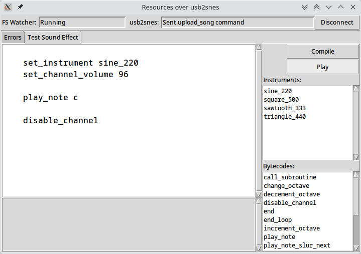
This GUI would allow me to quickly write out a sound effect, click a button and listen to it play on my console a frame or two later.
By focusing on sound effects first (which use the same bytecode format as songs, except sound effects use a single voice channel) I could quickly experiment with different bytecode ideas and see what worked with minimal changes to existing code.
When I was happy with the bytecode and confident it could be used to make music and sound effects, I spent 10 days adding sound effects to my Unnamed SNES Game. All audio testing was done using resources-over-usb2snes GUI and my 1-chip Super Famicom console. I'd tweak bytecode - modifying volumes, pitches, timing, and envelopes until the sounds become recognisable.
Despite the fact I was using simple example waveforms (noise, sawtooth, sine, square and triangle),
I was able to create a decent variety of sound effects. I mostly attribute this to portamento and
set_instrument_and_adsr instructions.
I am surprised how much character I can add to a sample by changing the ADSR envelope.
set_instrument_and_adsr triangle 8 6 6 12

play_note c+5 16
play_note c+5 16
play_note e5  16
play_note a5  16
play_note e6  24
set_instrument_and_adsr triangle 14 5 2 28

play_note c+5 16
play_note c+5 16
play_note e5  16
play_note a5  16
play_note e6  24
Now, sound effects can be written in bytecode or MML. Personally, I prefer bytecode over MML for most sound effects and MML for small jingle sound effects (dah-na-na-na-na!).
Bytecode
The bytecode instruction set went through many iterations and designs. It was originally an MML-like bytecode, where the audio driver managed the note-octave, semitone-offset and default-note-length values but I decided against it. Keeping track of these variables and ensuring it matched the behaviour of existing MML implementations added unwanted complexity to the audio driver.3 Nowadays, these MML settings are managed by the MML compiler and the various play-note bytecode instructions now require note-id and tick-count arguments.
One downside of this design is that I cannot implement MML ! substitution macros without
duplicating (inlining) the macro on very macro call. Instead, my MML syntax uses subroutines, where
each subroutine in the MML compiler has their own independent
octave/default-length/transpose/vibrato/etc settings. Allowing me to use ! commands without
duplication.
You can find the bytecode assembly syntax here.
Loops
My bytecode supports loops but it does not have a loop stack. Instead of a single start_loop,
skip_last_loop and end_loop instruction, there are 3 of each. The loop instructions are
identical, except they use different memory address to store their state. Imagine static stack
optimisation applied to a loop stack. The bytecode assembler is responsible for managing which loop
instruction (ie start_loop_1, start_loop_2, start_loop_3) to emit. As a bonus the assembler
will reject any code that exceeds the maximum nested loop count of 3.
As MML subroutines and MML channels can both contain nested loops, I needed a way to ensure loops cannot interfere with each other. My solution was nice and simple:
- Loops in MML channels start with a
start_loop_1instruction and nesting increments tostart_loop_3. - Loops in MML subroutines start with a
start_loop_3instruction and nesting decrements tostart_loop_1. - MML subroutines cannot call MML subroutines.
- The MML subroutines are compiled before the MML channels.
- The MML compiler outputs an error a subroutine call exceeds the maximum number of nested loops.
Timer
The timer went through a few redesigns. In the end I settled for using two timers, TIMER0 is
variable and set by the song and TIMER1 is fixed (at the fastest possible tempo) for sound
effects. This allows for songs to have an adjustable tempo while ensuring all sound effects are
played at the same tempo.
Early on I noticed some popping in my sound effects. Which was tracked down to the delay between key-off and key-on events being too small. It turns out the S-DSP release envelope is fixed and there needs to be a 8 millisecond delay between key-off and key-on events.4 I solved this issue by:
- Enforcing a minimum
TIMER0andTIMER1value of 64 (8ms) - Adding a
nextEventIsKeyOffflag to the timer. When a channel is sleeping and the countdown timer elapses:- If
nextEventIsKeyOffis set, the timer will send a key-off event and sleep for 1 more tick. - If
nextEventIsKeyOffis clear, the next bytecode will be executed.
- If
- Added a
keyOnMaskbit-field, that is cleared on key-on and set on key-off.- The
play_noteinstructions will only emit a key-on ifkeyOnMaskis set, preventing the bytecode from playing a note unless there was a key-off (and 1 tick key-off sleep) in a previous instruction.
- The
As a bonus, the nextEventIsKeyOff flag also controls if a note is slurred. If the channel did not
key-off, the note is slurred and the play_note instruction will change the channel's PITCH
register without emitting a key-on event.
Pitch effects
The bytecode supports 2 pitch effects, portamento and vibrato.
The portamento instruction extends a slurred note (or portamento) into a portamento pitch slide.
This is done by adding (or subtracting) a portamento_speed value to the PITCH register every
tick until the PITCH matches the target note.
The portamento instruction is very useful when creating sound effects.
set_volume 160
set_instrument_and_adsr triangle 10 6 3 28

play_note  e-5 no_keyoff      1
portamento g6  keyoff    +90 15
set_volume 48
set_instrument_and_adsr sawtooth 15 2 2 18

play_note  g3 no_keyoff      4
portamento c3 no_keyoff -30  8
portamento g3 keyoff    +20 20
The vibrato instructions will add or subtract a pitch_offset_per_tick value to the PITCH
register in a sawtooth pattern on every tick. The vibrato rate (wavelength of the sawtooth pattern)
is controlled by a quarter_wavelength_in_ticks variable.
set_volume 196
set_instrument_and_gain square I24

set_vibrato 60 12
play_note a4 240
MML
Why MML?
- I wanted some compatibility with an existing music format and MML is nicely documented with existing tutorials. Well, the base format is - with each variant having slightly different idiosyncrasies (mine included).
- MML loops and macros allow for artist intended song-data deduplication.
- If I used an existing tracker format I would not be able to get my audio driver to match the output of the tracker.
- I felt like it was easier to create a GUI using a text-based format compared to creating a tracker GUI.
I based my MML on PMD MML, which very nicely documented and includes lots of examples and cautions. Naturally, PMD does things that my driver cannot do (FM synthesis) and my driver has features that do not match PMD (echo, vibrato, ADSR register values). This results in a new variant of MML and you find the syntax here.
Development of the prototype MML compiler was written in python and tested exclusively on my Super Famicom consoles. I not test on an emulator because I never connected the python MML compiler to my Unnamed SNES Game's resource subsystem. To test the MML compiler, I inputted MML into the resources-over-usb2snes GUI, clicked the Play Song button and listened to the output from the console.

This is how I tested the MML compiler before I started the rust GUI.
#Title Ode To Joy (G Major)
#Composer Ludwig van Beethoven
#Tempo 144

@1 triangle

!repeated_notes l4 o4 b b > c d d c < b a g g a b

A @1 l4 o4 v16
A !repeated_notes b. a8 a2
A !repeated_notes a. g8 g2
A a a b g a b8 > c8 < b g a b8 > c8 < b a g a d2
A !repeated_notes a. g8 g2
One of the first songs I played on my audio driver.
Rust GUI
Six months ago, the audio driver was at a state where I could make sound effects and music but I'm horrible at making music. I also want other people to make music with my audio driver. I was not certain how easily I could tweak my tooling to work on someone else's machine (especially since it requires setting up QUsb2Snes and installing a few python modules). I needed to create a Windows/Linux/MacOS GUI.
I chose to code it in rust as it gave me an excuse to learn rust. The GUI took a lot longer to write then I expected. Not because I'm learning a new programming language (although that did slow me down a bit) but because I did not realise the amount of effort it takes to make a fully featured and well defined GUI.
The GUI includes an audio emulator, based on modified ares source code, allowing the user to listen to the sample, sound effect or music while editing them.
While writing the GUI I spent a bit of time thinking about ideas for making MML editing easier. Here's a few useful things I added to my GUI:
Section length tracking
A few MML tutorials I found recommended you enable total tick count, write the song in sections and constantly check the total tick count to verify the channels are synchronised.
My GUI does that automatically. If the MML is compiled successfully, it lists the tick count for each channel. You can also divide an MML file into sections with a double-semicolon ;; comment.
@1 piano

ABC @1

;; Major triad
A o4  c  d  e   f  g   a  b  r
B o4  e  f+ g+  a  b  >c+ d+ r
C o4  g  a  b  >c  d   e  f+ r

;; Minor triad
A o4  c  d  e   f  g   a  b  r
B o4  e- f  g   a- b- >c  d  r
C o4  g  a  b  >c  d   e  f+ r

;; Augmented triad
A o4  c  d   e  f  g   a  b  r
B o4  e  f+  g+ a  b  >c+ d+ r
C o4  g+ a+ >c  c+ d+  f  g  r
MML compiled successfully: 190 bytes (+256 echo buffer bytes)

Duration: 0:13
                | Channel A | Channel B | Channel C |
Major triad     |       192 |       192 |       192 |
Minor triad     |       384 |       384 |       384 |
Augmented triad |       576 |       576 |       576 |
Note playback highlighting
When researching MML variants I came across mmlgui, a GUI for ctrmml which had a very nice feature where it highlighted the current note as it played the song. After seeing how useful it can be, I realised I needed to add it to my GUI.

Cursor position status bar
I spent some time porting a public domain song with the aid of midi2smw to try and find some pain points when creating MML. I kept getting lost, not knowing where I was in the song while trying to navigate multiple channels.
This lead to the creation of a status bar that shows the MML state (tick counter, octave, default note-length, semitone offset, etc) of the text-cursor on the bottom of the window.

Play at cursor position
After I had created a mapping of character-indexes to tick-counts, I added a button that allowed the user to start playback at the text-cursor position.
To avoid adding unnecessary complexity to the MML compiler or the audio-driver I implemented this feature by writing a second bytecode interpreter in rust. The interpreter runs through the bytecode until the interpreter's tick-count match the tick-count in the text-editor.5 Then the output of the interpreter is written into the emulated audio-driver's Audio-RAM and the emulator starts playing music exactly where I want to start it.
The rust interpreter was tested by running the audio driver in an emulator, pausing the emulator every few ticks and repeatedly comparing emulator's audio-RAM against the rust interpreter output. As a bonus this also tests the spc700 bytecode interpreter against the rust interpreter.
Test instrument widget
While I was editing MML, I found myself wanting a way to quickly test what an ADSR envelope sounds like without going to all the hassle of creating a new MML instrument. To that end I added a test instrument widget, which provides a quick way to test samples and envelopes at the same time.

I'm implementing virtual channels after all
While testing my audio driver, KungFuFurby noticed popping when the volume or pan is changed immediately after a key-off event. This shouldn't be happening, so I made a test and looked at the waveform.

The first note suddenly jumps in volume during the key-off release envelope instead of slowly reducing in volume.
Oh dear, it looks like I'm changing the volume in the middle of the key-off tick. I completely forgot that I shouldn't modify the channel's VxVOL or SCRN registers during the Release envelope and it's something I did not test for.
I had 3 options to fix this:
- Add a second tick delay after all key-off events (something I did not want to do).
- Delay all
SCRN&VxVOLwrites to the start of the next tick. - Delay all DSP register writes to the start if the next tick (step 1 to implementing virtual channels).
After sleeping on it I decided to add virtual channels to my audio driver. However, I have not yet implemented channel stealing sound effects, so music is still limited to 6 channels. I wanted to finish the S-CPU interfacing code first, so I can write a bunch of tests to confirm the channel-stealing logic works correctly.
As part of this decision I did some back-of-the-napkin calculations. It would cost me ~80 cycles
per channel to copy the virtual registers from audio-RAM to S-DSP. That's 16% of my CPU budget (32
TIMER0 ticks6). My audio driver is already fast, I do not believe this 16% extra
CPU usage would result in lag in normal music playback.
I also added a dirty flag to the virtual channels. This will add some jitter to key-on events as I
need to write to the S-DSP voice registers before writing to KON. Assuming 0-8 channels can be
updated at once, back-of-the-napkin math suggests ~25 samples (0.78ms) of jitter, which I doubt is
noticeable.
I found a race condition
While testing a new feature I added for KungFuFurby (Gain mode commands in MML), I encountered a race condition when switching from ADSR to GAIN envelops while a note is playing.
Why would I want to change the envelope in the middle of note? The release envelope on the S-DSP is fixed. To create a custom release envelope you could change the envelope to GAIN in linear-decay or exponential-decay mode.

| S-DSP Voice Register | d7 | d6 | d5 | d4 | d3 | d2 | d1 | d0 | |
|---|---|---|---|---|---|---|---|---|---|
| $x5 | ADSR1 | ADSR enable | Decay Rate | Attack Rate | |||||
| $x6 | ADSR2 | Sustain Level | Sustain Rate | ||||||
| $x7 | GAIN | 0 | Fixed envelope | ||||||
| 1 | Mode | Rate | |||||||
This race condition was caused by me writing to the following registers in the following order:
- Write
0toADSR1to disable ADSR. - Write to
GAINto set the GAIN envelope.
As such, there exists a few cycles where ADSR is disabled and the GAIN register holds the previous
GAIN value.
In the above waveform, I'm repeating two notes with two different envelopes:
- The first note (the rectangle) is played with a fixed GAIN envelope (at max value).
- The second note (the kite) is played with an ADSR envelope, then switches to a linear-decay GAIN envelope in the middle of the note.
If DSP reads the envelope before the GAIN register has been updated, it changes the envelope to
max for a single sample - glitching the entire envelope.
The fix for this race condition is simple. Write to the GAIN or ADSR2 register before the
ADSR1 register.
What's next
The Terrific Audio Driver is nearly complete, the major features that remain are:
- ca65 S-CPU code.
- PvSnesLib S-CPU code.
- Channel stealing sound effects - so I can eliminate the 6 music channels limit.
After that I'm going to practice making music and sound effects (while doing other SNESdev things) for a few months. If no one discovers any issues with the bytecode or MML syntax by then I will stabilise the syntaxes and data-formats and declare the Terrific Audio Driver production ready (releasing v1.0.0).
Special thanks
I would like to thank the following people, whose creations or assistance have helped me create the Terrific Audio Driver:
- Near - for creating ares.
- Sour - for creating Mesen.
- Anomie - for writing Anomie's S-DSP Doc, an in-depth technical document on the S-DSP.
- eggboycolor - for creating the wiz programming language.
- krom (Peter Lemon) - for writing a few SPC700 demos, which helped me to learn SPC700 assembly and provided a nice example for how to access the S-DSP registers.
- Douglas Fraker - for creating and releasing a lot of free BRR samples
- KungFuFurby - for beta testing my audio driver.
- The people on the SNES Development Discord who have helped and offered suggestions when I wanted feedback or got stuck.
- Ian Karlsson - for creating mmlgui, whose note tracking feature was the deciding factor for choosing MML over writing a custom tracker.
- M.Kajihara - for creating the Professional Music Driver (PMD).
- Blaze and Pigu - for translating the Professional Music Driver (PMD) manual.
- The rust team - for creating rust.
- All of the creators and maintainers of the third party libraries used by the Terrific Audio Driver.
-
Why terrific? Because my audio driver is not Super. ↩
-
A split word table splits a 16-bit word table into two 8-bit byte high and low tables. This optimisation allows me to index 256 entries with an 8-bit index and makes the code smaller and faster. ↩
-
PMD's documentation states that octave/default-length/transpose/etc settings restart at the start of a loop and that settings after the loop are the settings at the end of the loop not the settings at the
:skip-last-loop command.
For exampleo4 [ c : >d ]2 ewill outputo4 c | o5 d | o4 c | o5 e. ↩ -
There's also some complexity to how the
KONandKOFFregisters are read by the S-DSP that can result in some dropped notes that is documented in Anomie's S-DSP Doc. ↩ -
Modern computers are crazy fast. The rust interpreter takes 17.72µs - 36.77µs to run though a 6-channel 4m45s song (
gimo_297) on my PC. ↩ -
The minimum
TIMER0value my audio-drive will accept is 64. I'm using a 32TIMER0ticks CPU-time budget to be cautious. ↩